
Research
Stress analysis of SiC devices and modeling the effect of mechanical stress on bipolar degradation
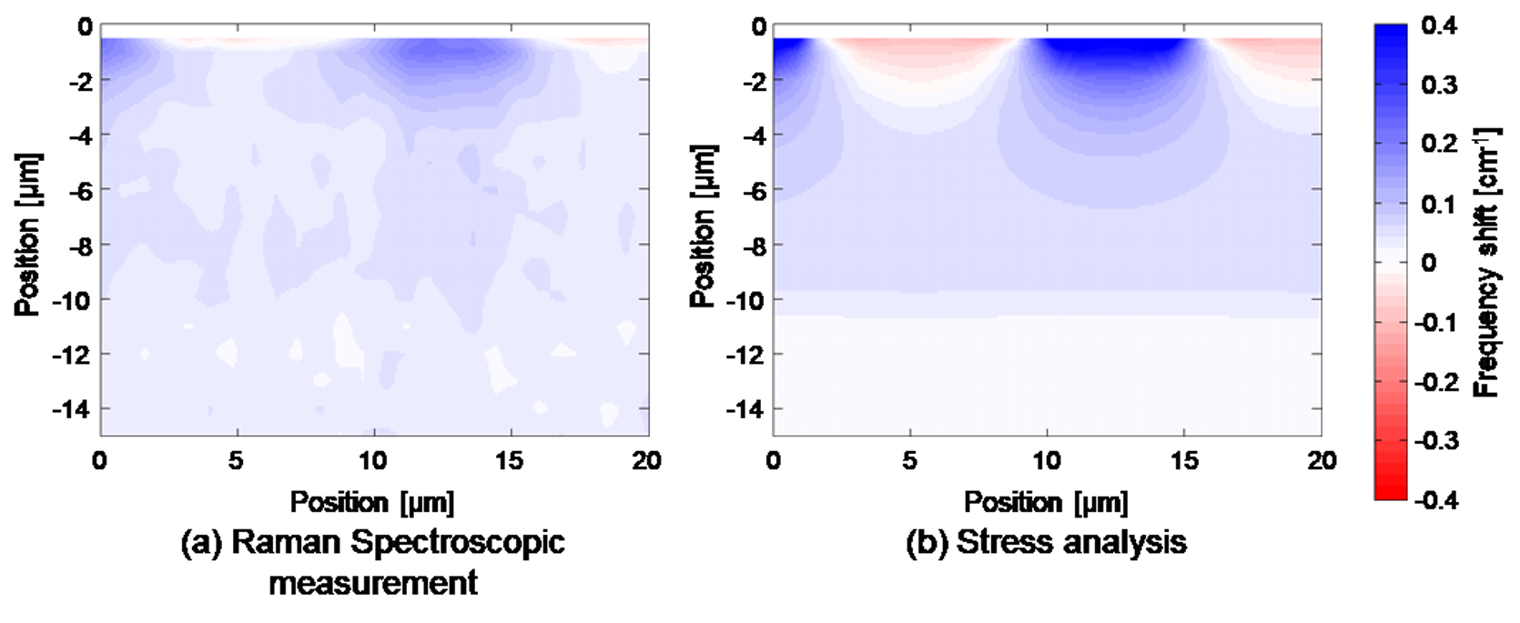
Silicon carbide (SiC), a wide-bandgap semiconductor, is gaining attention as a material for next-generation power devices due to its superior electrical properties. During the manufacturing process of semiconductor devices, complex stress distributions often emerge, leading to reliability issues. Additionally, bipolar degradation—a phenomenon where stacking faults rapidly expand under current flow—poses a significant challenge for bipolar devices.
This study aims to enhance the mechanical reliability of 4H-SiC power devices by developing a method to analyze stress distribution and model its impact on bipolar degradation. While stress in semiconductors can be experimentally evaluated using Raman spectroscopy, this method alone cannot resolve all six stress components of the stress tensor. To overcome this limitation, we integrated finite element analysis (FEA), simulating the fabrication process of 4H-SiC devices, with Raman spectroscopy. The FEA results were validated against experimental measurements [1].
Additionally, we developed a quantitative model to describe the effect of mechanical stress on bipolar degradation. Through a combination of integrating experiments, device simulations (TCAD), and FEM analysis, we successfully captured the relationship between stress and the critical carrier density, a key parameter for predicting the onset of bipolar degradation [2].
Reference
- H. Sakakima, S. Takamoto, Y. Murakami, A. Hatano, A. Goryu, K. Hirohata, and S. Izumi, “Development of a method to evaluate the stress distribution in 4H-SiC power devices”, Japanese Journal of Applied Physics 57, 106602 (2018).
- H. Sakakima, A. Goryu, A. Kano, A. Hatano, K. Hirohata, and S. Izumi, “Modeling the effect of mechanical stress on bipolar degradation in 4H-SiC power devices”, Journal of Applied Physics 128, 250701 (2020).
Atomic-scale modeling of strength and crystal defects in SiC crystals
To ensure and improve the mechanical reliability of power devices, it is crucial to understand the materials that compose them. As such, we have conducted extensive studies on the mechanical properties of materials and crystal defects, utilizing first-principles calculations and molecular dynamics methods. In particular, we have focused on stacking faults, a key challenge for the reliability of SiC power devices. Our research has involved analyzing the temperature dependence of stacking fault energy through first-principles calculations, evaluating the accuracy of predictions using different functionals, and investigating how the presence of excess carriers affects the stacking fault energy. Currently, our efforts are centered on studying the impact of excess carriers on material strength, aiming to gain a deeper understanding of how these carriers influence the mechanical properties and reliability of SiC devices.

Reference
- H. Sakakima, S. Takamoto, A. Hatano, and S. Izumi, “Temperature-dependent stacking fault energies of 4H-SiC: A first-principles study”, Journal of Applied Physics 127, 125703 (2020).
- H. Sakakima, A. Hatano, S. Izumi, “Comparative study of the effect of van der Waals interactions on stacking fault energies in SiC”, Journal of Applied Physics 130, 215701 (2021)
- H. Sakakima and S. Izumi, “First-principles investigation of the effects of excess carriers on the polytype stability and stacking fault energies of SiC,” Journal of Applied Physics 134, 155103 (2023).
- H. Sakakima, S. Izumi, “Carrier-doping effect on strength and deformations in group-IV crystals,” International Journal of Mechanical Sciences 293,110169 (2025).
Reaction pathway analysis for BPD-TED conversion in 4H-SiC
4H-SiC has been widely used as a next-generation power-device material. It is known that basal plane dislocations (BPDs) are problematic since they degrade the performance of the devices. Most BPDs are converted into harmless threading edge dislocations (TEDs) by using a step-controlled epitaxy. However, the mechanism underlying BPD−TED conversion is still not clear since this conversion occurs in the vicinity of the surface. Therefore, the purpose of this study is to elucidate the mechanism using molecular dynamics.
It is known that BPDs in SiC are dissociated into two Shockley partials. Therefore, the contraction of partial BPDs to a perfect BPD is a necessary step for the conversion to TEDs. After the contraction, a perfect BPD converts a TED by the cross slip. In this study, we first analyzed the mobility of partial screw BPDs in order to clarify the effect of the surface on the contraction using the nudged elastic band (NEB) method for the reaction pathway analysis. This method enables us to calculate the activation energies of the mobility of the dislocations. We found that the contraction of BPDs easily occurs in the vicinity of the surface. Next, we analyzed the reaction pathways for the cross slip from BPDs to TEDs. We found that the cross slip easily occurs in the vicinity of the surface. Therefore, the distance from the surface to the BPDs has a great effect on the BPD-TED conversion.
Finally, we performed an MD simulation of BPD-TED conversion. We found the conversion occurs in the vicinity of the surface.
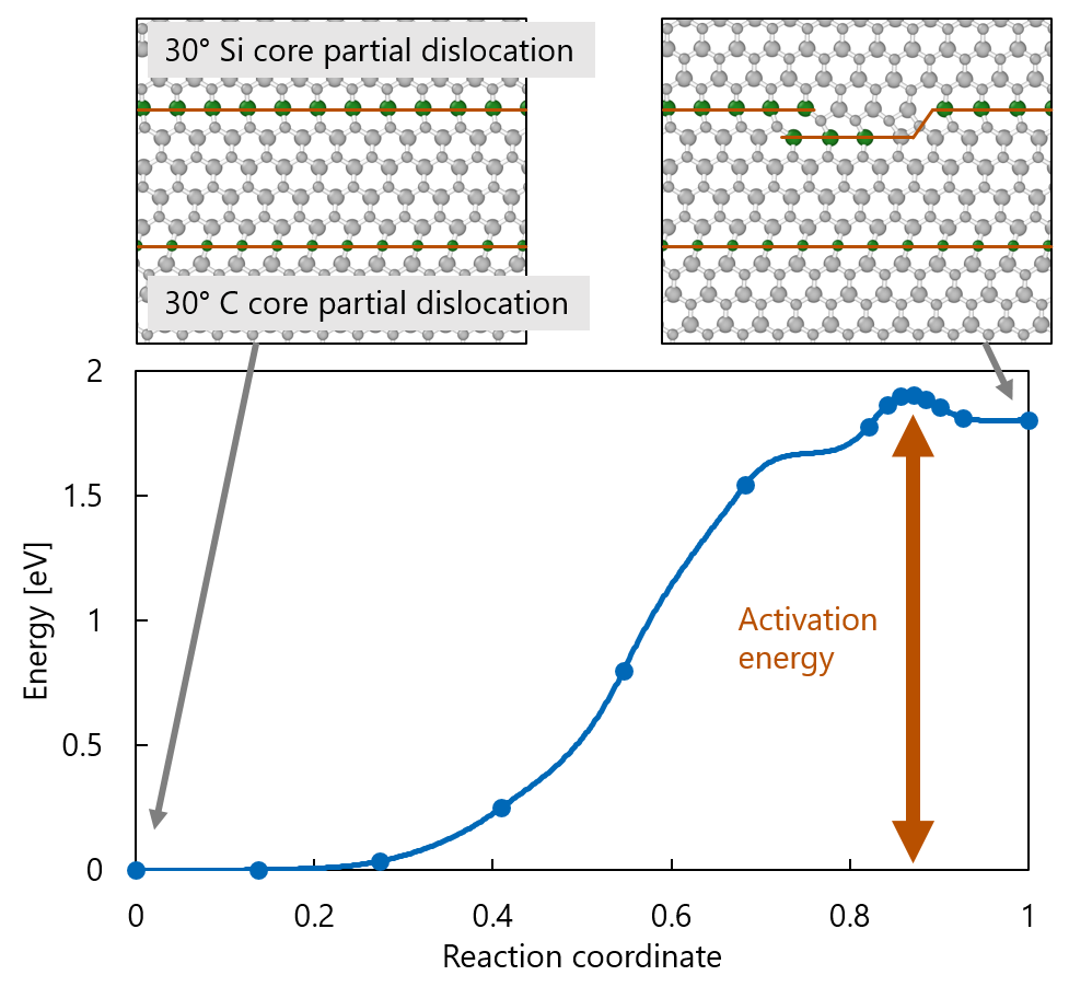
Example of the energy curve calculated by reaction pathway analysis
MD simulation for BPD-TED conversion
Reference
- Yohei Tamura, Hiroki Sakakima, So Takamoto, Asuka Hatano, Satoshi Izumi, “Reaction pathway analysis for the conversion of perfect screw basal plane dislocation to threading edge dislocation in 4H-SiC”, Jpn. J. Appl. Phys. 58 081005 (2019)
- Atsuo Hirano, Hiroki Sakakima, Asuka Hatano, Satoshi Izumi, “Reaction pathway analysis for the contraction of 4H-SiC partial-dislocations pair in the vicinity of surface”, Jpn. J. Appl. Phys. 60 085502 (2021)
Application of Molecular Dynamics Simulation to Material Strength Problems
Our research also leverages molecular dynamics simulations, with a strong focus on the application of high-precision interatomic potentials and developing both empirical and machine-learning-based interatomic potentials. Recently, a general-purpose high-precision interatomic potential capable of modeling arbitrary materials has been proposed using deep learning. This breakthrough is expected to significantly extend the applicability of molecular dynamics to phenomena that were previously challenging to simulate.
We are utilizing this advanced potential to investigate the atomic network structure and mechanical properties of complex multi-element materials, which have traditionally been difficult to analyze. Currently, our focus is on SiO2, a material extensively used in insulating films for semiconductor devices. Our research examines how the incorporation of carbon (C) and nitrogen (N) influences its mechanical strength, as well as the aggregation behavior of carbon atoms into C clusters, which plays a crucial role in determining material properties.

Reference
- Hiroki Sakakima, Keigo Ogawa, Sakurako Miyazaki, Satoshi Izumi, “Exploration of the Mechanical Properties of Carbon-Incorporated Amorphous Silica Using a Universal Neural Network Potential,” Journal of Applied Physics 135, 085104 (2024).
- Sakurako Miyazaki, Hiroki Sakakima, Keigo Ogawa, Satoshi Izumi, “Molecular Dynamics Study of the Effect of Composition on Elastic Properties of Silicon Oxynitride Films,” Japanese Journal of Applied Physics 63(11), 115502 (2024).
A Cardiomyocyte model integrating Electrophysiology and Mechanics
Contraction of every cardiomyocyte realizes heartbeat, which is vital for our lives. Morphological disruption of subcellular structures has been reported in heart diseases, although the complex nature of the cardiac electrophysiology–contraction coupling process makes it difficult to experimentally establish causal relationships between subcellular disruption and cardiac dysfunction. We developed electrophysiology-mechanics-coupling finite element model of cardiomyocyte in which subcellular structures are modeled and realistically arranged. This model reproduced the Ca2+ transients and contraction observed in experimental studies [1]. We investigated asynchronous contraction caused by deletion of t-tubules [2], the importance of juxtaposition of mitochondria and Ca2+ release site on cardiac energy balance [3], and distinct functional roles of mitochondrial subpopulations [4]. Our integrated model of cardiomyocyte provides a powerful tool for the study of cardiac function by expanding the temporal and spatial resolution beyond the limit in experimental approaches.
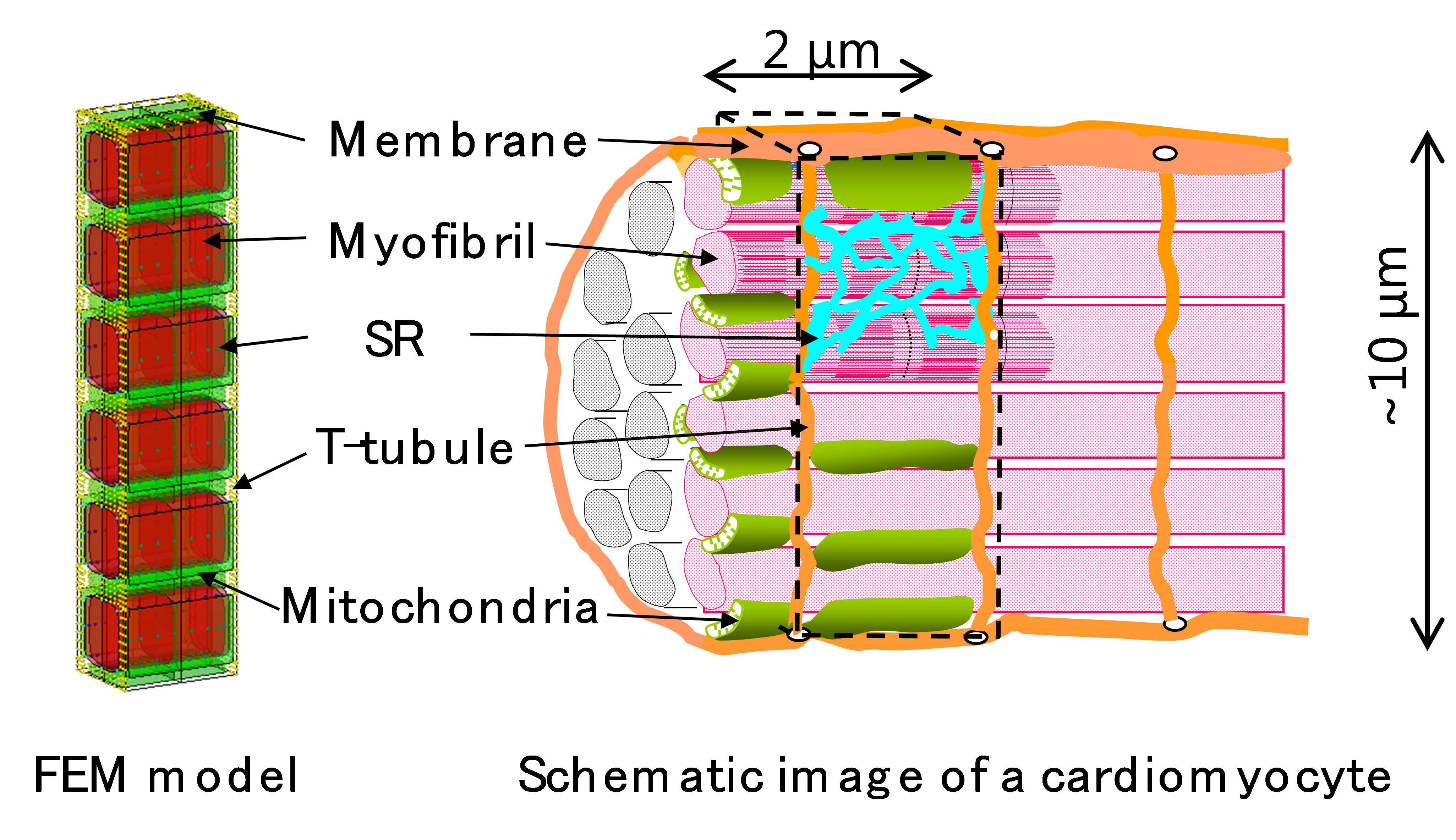
3D presentation of finite element model and schematics of a cardiomyocyte.
Reference
- Hatano et al. A 3-D simulation model of cardiomyocyte integrating excitation-contraction coupling and metabolism. Biophysical Journal, 101(11):2601-2610, 2011
- Hatano et al. Critical role of cardiac t-tubule system for the maintenance of contractile function revealed by a 3D integrated model of cardiomyocytes. Journal of Biomechanics, 45(5):815-823, 2012
- Hatano et al. Mitochondrial Colocalization with Ca2+ Release Sites is Crucial to Cardiac Metabolism. Biophysical Journal, 104(2):496-504, 2013
- Hatano et al. Distinct Functional Roles of Cardiac Mitochondrial Subpopulations Revealed by a 3D Simulation Model. Biophysical Journal, 108(11):2732–2739, 2015
Isolation and reconstruction of cardiac mitochondria from SBEM images using a deep learning-based method
Mitochondrial morphological defects are a common feature of diseased cardiac myocytes. However, quantitative assessment of mitochondrial morphology is limited by the time-consuming manual segmentation of electron micrograph (EM) images. To advance understanding of the relation between morphological defects and dysfunction, an efficient morphological reconstruction method is desired to enable isolation and reconstruction of mitochondria from EM images.
We propose a new method for isolating and reconstructing single mitochondria from serial block-face scanning EM (SBEM) images. CDeep3M, a cloud-based deep learning network for EM images, was used to segment mitochondrial interior volumes and boundaries. Post-processing was performed using both the predicted interior volume and exterior boundary to isolate and reconstruct individual mitochondria. Series of SBEM images from two separate cardiac myocytes were processed. The highest F1-score was 95% using 50 training datasets, greater than that for previously reported automated methods and comparable to manual segmentations. Accuracy of separation of individual mitochondria was 80% on a pixel basis. A total of 2315 mitochondria in the two series of SBEM images were evaluated with a mean volume of 0.78 µm3.
This new automated segmentation and separation method can help quantitate mitochondrial morphology and improve understanding of myocyte structure–function relationships.
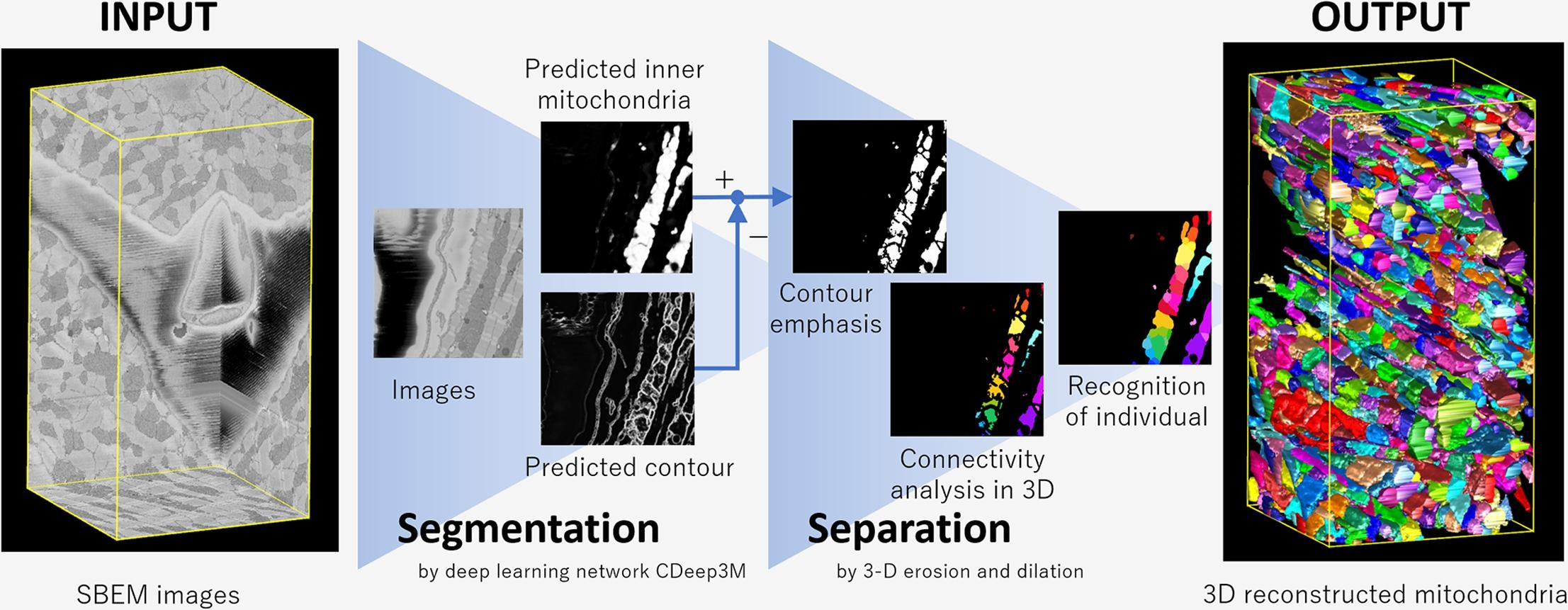
A schematic diagram of the whole process of 3-D reconstruction of mitochondria
Reference
- Asuka Hatano, Makoto Someya, Hiroaki Tanaka, Hiroki Sakakima, Satoshi Izumi, Masahiko Hoshijima, Mark Ellisman, Andrew D. McCulloch, “Isolation and reconstruction of cardiac mitochondria from SBEM images using a deep learning-based method”, Journal of Structural Biology, 214, 107806(2022)
Wear prediction of front rod bearing of railroad switch
When a train passes through the railroad joint at the heel of the tongue rail of the railroad switch, impact vibration is induced due to the step difference of the joint. This impact vibration transfers to the front rod, which is the attachment device located on the toe of tongue rail and connected with position checker device, induces the wear of bearing and resulting switching failure. In order to clarify the mechanism of the wear, we have developed the finite element model of the normal railroad switch and the special railroad switch. The models are validated by the acceleration and axial force of the front rod measured in track open for traffic. On the other hand, we calculated the coefficient of wear amount of bearing from the wear test. Combining with the results of finite element analysis and the coefficient of wear amount, we predicted the wear amount of the front rod in the track. Our final goal is to propose the appropriate maintenance schedule for any other type of railroad switch under various working conditions.
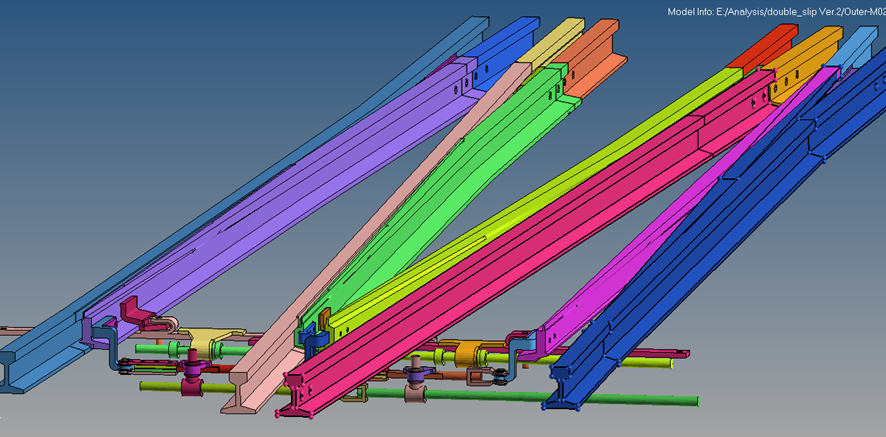
FEM model of crossing overview
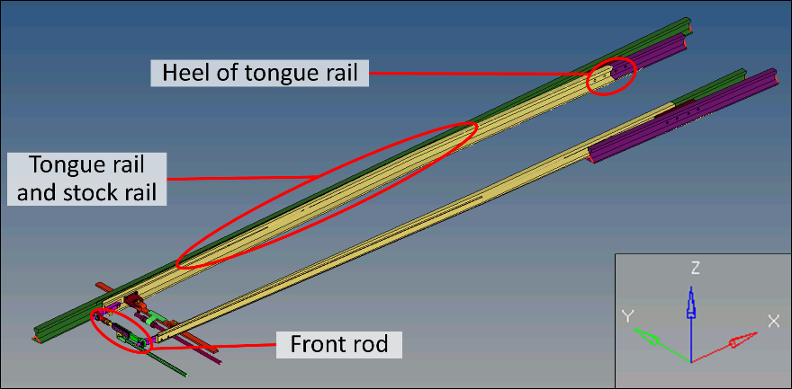
FEM model of crossing railroad switch device
Reference
- Yuki Kondo, Takuma Shimamoto, Asuka Hatano, Satoshi Izumi, Shinsuke Sakai, Hirotoshi Higuchi, Masahiko Suzuki, Takashi Kato, "Finite element modelling for the wear prediction of front rod of railroad switch due to the impact vibration caused by train passage", Transactions of the JSME (in Japanese), Vol. 81, No. 832 (2015), DOI:10.1299/transjsme.15-00286.
- Takuma Shimamoto, Keita Tadokoro, Asuka Hatano, Satoshi Izumi, Shinsuke Sakai, Yoshiyuki Nino, Masahiko Suzuki, Toshiyuki Kaneda, "Finite element modelling for the wear prediction of front rod of special layout railroad switch due to the vibration caused by train passage", Transactions of the JSME (in Japanese), Vol. 85, No. 873, pp. 18-00414 (2019) DOI: 10.1299/transjsme.18-00414
Finite Element Analysis for bolt-nut joint system
Threaded fasteners are widely used in mechanical structures since the disassembly for maintenance is easy without much cost. However, vibration induced loosing due to dynamic loading has been an unsolved subject over past six decades. We have investigated the mechanisms of tightening process and loosening process due to shear loading in the framework of the three-dimensional finite element method (FEM). Results are compared with the conventional theories based on the material mechanics and experimental results. We found some new aspects for threaded fastener theory. Good qualitative agreement is observed between FEM and experiments with respect to the behavior of loosening subjected to shear loading, such as hysteresis loop of transverse displacement and shear load and critical slip width for complete bolt-head slip. It is found that loosening initiates when complete thread slip has occurred prior to the head slip, which has been considered as an initiation point of loosening. Therefore, the modification of the design of threaded fastener is needed.
https://www.fml.t.u-tokyo.ac.jp/~izumi/Bolt/
Bolt-nut loosening simulation (contour indicates horizontal displacement)
Bolt-nut tightening simulation (contour indicates axial stress)
Bolt-nut loosening simulation
Machine learning surrogate model for finite element analysis of railway vehicles
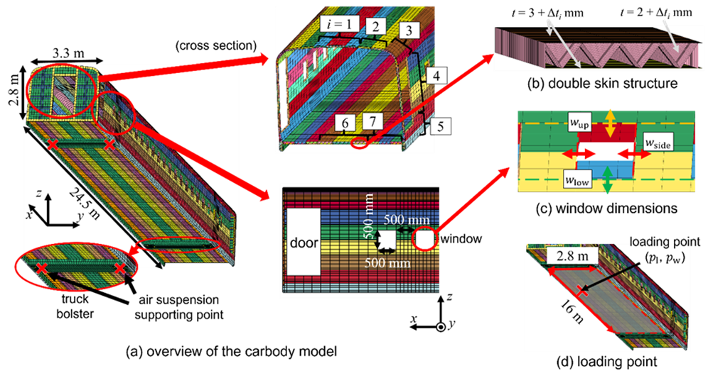
The carbody of railway vehicles typically forms a “double-skin structure” with a corrugated cross-section created by integrating plates and frames. In the early stages of railway vehicle design, finite element analyses (FEA) are repeatedly performed while adjusting design variables such as plate thickness, window dimensions, and under-floor equipment installation positions to achieve the desired performance. However, this repetitive FEA process with the detailed, large, and complex vehicle structures is computationally demanding and time-consuming. This is not only due to the simulations themselves but also because of the substantial effort required for pre-processing tasks such as geometry modification and meshing.
This study aims to reduce the burden associated with frequent changes in geometry and design conditions by developing a machine learning-based surrogate model. A surrogate model approximates and learns the relationship between input and output variables, enabling direct predictions of outputs without performing computationally intensive numerical calculations. We have developed a surrogate model which can predict key quantities related to the first vertical bending mode — such as the maximum deflection, deformation and stress distributions, natural frequencies, and mode shapes under distributed loads — without executing finite element analysis.
Reference
- Kohei Fukumoto, Hiroki Sakakima, Ryo Furutani, Takeshi Kawasaki and Satoshi Izumi, “Machine learning surrogate model for finite element analysis of railway vehicles using principal component analysis and multilayer perceptron”, Transactions of the JSME (in Japanese), Vol.90, No.937 (2024). [DOI: 10.1299/transjsme.24-00133]
Finite element simplified modeling of bolted joints in railway vehicles
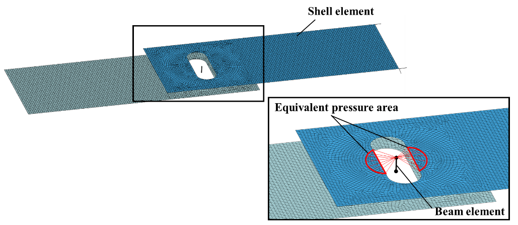
Bolted fasteners are used in a wide range of mechanical structures, such as railway vehicles. Since bolted fasteners can be weak points in terms of strength, sufficient reliability is required in terms of strength and vibration characteristics. However, detailed modeling of all bolted fasteners is not realistic from the viewpoint of the calculation cost for the design of structures with many bolted connections, so a simple and accurate model is required.
Therefore, we have proposed a simplified modeling method for plate joints as a basic study. We have modeled the bolted fasteners with beam elements and the plates with shell elements, and reproduced the stiffness, strain distribution, and natural frequencies with high accuracy by applying rigid body restraints and RBE3 restraints to the areas where compressive forces propagate due to bolting (equivalent pressure area).
Furthermore, the simplified modeling method has been applied to attachment rails. As in the case of plate joints, the bolted fasteners are modeled with beam elements and the other members with shell elements, and the equivalent pressure area is constrained to accurately predict the stiffness, strain distribution, and natural frequencies.
Finite element modeling of wire rope
Elevator wire rope
We have developed the finite element modeling for the elevator wire rope 8×S(19) to reproduce the stiffnesses in both axial and radial directions. In addition, compression test to measure the radial-direction stiffnesses of strand, fiber core and wire rope have been newly proposed.
Firstly, from the experimental result of radial compression test of strand, it is found that the radial-direction stiffness(Apparent young modulus : 20GPa) is greatly lower than axial-direction one(Apparent young modulus : 150GPa). It is also showed that the radial load fills the inner gap of strand and increases the stiffness from the experimental and analytical results. This indicates the importance of reproduction of the contact situation between wires for the finite element modeling. Our finite element model well reproduces the stiffness of strand in the both directions.
Secondary, from the experimental result of radial compression test of fiber core, it is found that load-displacement curve of fiber core in the radial direction involves a hysteresis, reflecting the mechanical property of fiber. To reproduce the stiffness just after unloading from compression, the fiber core is modeled as an elastic body with the Young modulus of 300 MPa.
Finally, from the experimental result of radial compression test of wire rope, load-displacement curve of wire rope in the radial direction involves a hysteresis as well as the fiber core and the stiffness is similar with that of the fiber core. Besides, the stiffness increases as the tension of wire rope is increased. This is due to the strong contacts between wires and between strand and fiber core. The finite element model of fiber core reproduces its real shape bitten into by strand. Assembled finite element model of wire rope well reproduces the stiffness of wire rope in the both directions.
Crane wire rope
We have also developed the finite element modeling for the crane wire rope IWRC 6×Fi(29). The difference between IWRC 6×Fi(29) and 8×S(19) is that rope core of IWRC 6×Fi(29) consists of wires. Owing to many contact points between wires, higher frictional force is caused in IWRC 6×Fi(29). It is necessary to reproduce the internal contact state in detail.
From the comparison of tests and analyses, finite element models of strand, rope core and wire rope well reproduce the stiffness in axial and radial directions. To evaluate the fatigue of wires based on actual operation, we preformed the simulation reproducing the state of being wound up by pulley. It is found that large stress amplitude is occurred at wires that are broken in fatigue bending test. There is a high probability that breaking of wires results from fatigue damage.
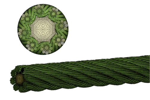
Elevator wire rope : 8×S(19)
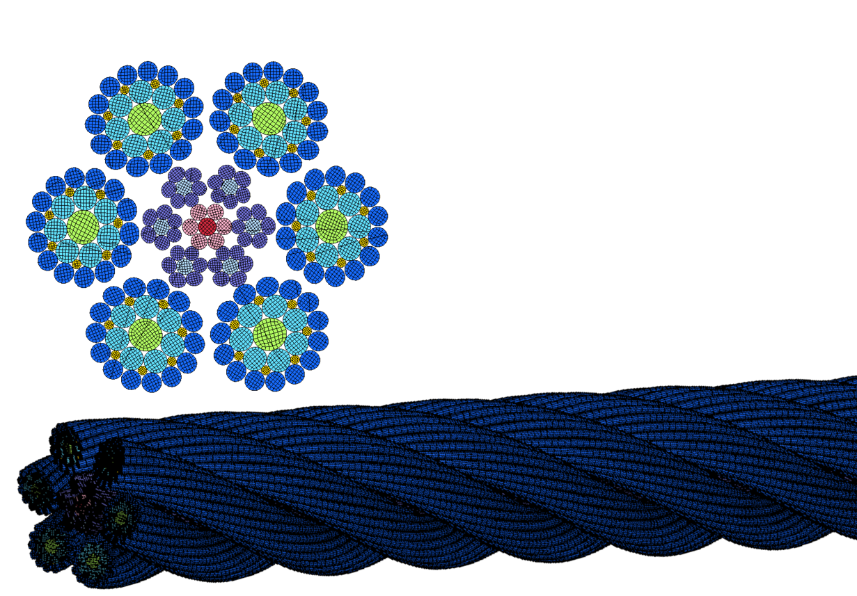
Crane wire rope : IWRC 6×Fi(29)
Reference
- Satoshi Izumi, Tatsuya Nakatani, Niina Ota, Asuka Hatano, Kenta Yamagiwa, "Finite element modeling of elevator wire rope to reproduce the radial-direction stiffness", Transactions of the JSME (in Japanese), Vol. 87, No. 896 (2021) DOI: 10.1299/transjsme.20-00418
Development of multi-scale simulation to overcome large time scale and spatial scale and its application to the problem of materials strength
Our research aims to the development of multi-scale simulation tool to combine finite element method (FEM), dislocation dynamics (DD), molecular dynamics (MD) and electrical state calculation. Especially, we focus on the novel method to overcome large time scale and spatial scale. We apply our tools to the phenomena of dislocation nucleation and propagation and the delamination of thin film in the fields of semiconductor devices and electronic devices.
To connect macro scale (continuum level) and nano scale (atomic level), we have to overcome 9- order gap, i.e. from m to nm and from sec to nsec.
For solving the spatial scale problem, we have developed the FEM-MD combined method and applied to the delamination problems of thin films. Fig. 1 shows the nano-indentation model of delamination test. The bottom part is modeled by FEM. Fig. 2 is the result, showing the similar mode of delamination as experimental result.
For solving the time scale problem, we try to develop the method for finding reaction pathway by using NEB (Nudged Elastic Band) method. Fig. 3 shows the dislocation nucleation from a sharp corner in silicon. A dislocation is nucleated under a critical stress (athermal stress). Fig. 4 shows the dependence of the activation energy on stress (Shuffle-set versus Glide-set). That curve provides useful knowledge with the atomistic view of dislocation nucleation problem having the long-range time scale inaccessible to the molecular dynamics. Moreover, combing the result with dislocation dynamics enables us to see the subsequent propagation and multiplication process(Fig. 5).
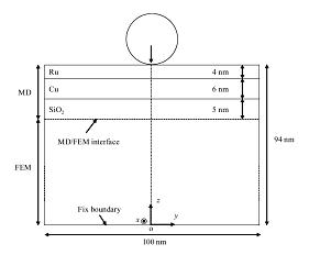
Fig.1 FEM-MD model for thin-film delamination test using nano-indentation
Fig.2 Simulation result of thin-film delamination using nano-indentation
Fig.3 Dislocation nucleation from a sharp corner in silicon; molecular dynamics calculation
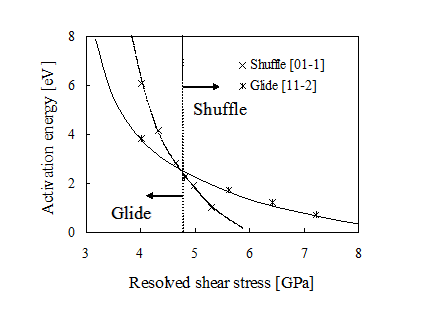
Fig.4 Dependence of activation energy for dislocation nucleation on stress
(Comparison of Glide-set dislocation with Shuffle-set one)
Fig.5 Dislocation Dynamics Simulation for semiconductor device
Reference
- [1] S. Hara, T. Kumagai, S. Izumi, S. Sakai, “Multiscale analysis on the onset of nanoindentation-induced delamination: Effect of high-modulus Ru overlayer”, Acta Materialia 57 (2009) pp. 4209-4216.
- [2] Satoshi. Izumi, Sidney. Yip, “Dislocation Nucleation from a Sharp Corner in Silicon”, J. Appl. Phys. 104 (2008) 033513.
- [3] K. Shima, S. Izumi and S. Sakai,“Reaction Pathway Analysis for Dislocation Nucleation from a Sharp Corner in Silicon: Glide Set versus Shuffle Set”, J. Appl. Phys., 108 (2010), 063504.
- [4] S. Izumi, T. Miyake, S. Sakai, H. Ohta, “Application of three-dimensional dislocation dynamics simulation to the STI semiconductor structure”, Materials Science Engineering A, 395,1-2 (2005) pp.62-69.
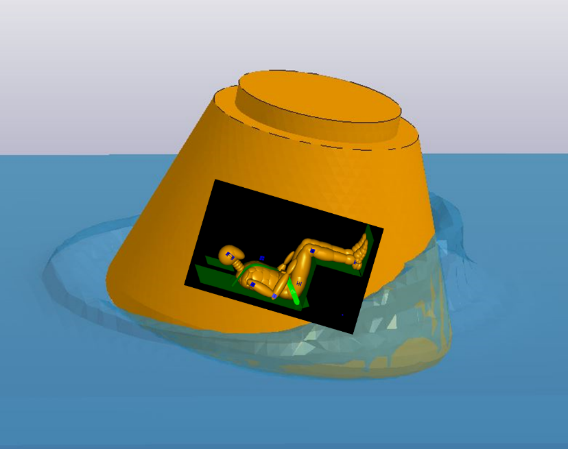
Human safety evaluation in launch abort system
In order to realize the human space flight system, it is essential to improve the human safety evaluation method. Therefore, injury risk evaluation when the human body is exposed to the impact of launch abort system(LAS) is needed.
In the field of the space industry, we have evaluated the injury risk by mass analysis. We also have established the injury evaluation method by multibody dynamics analysis and finite element method, which are highly accurate. This injury evaluation method made it possible to consider the effect of seats and estimate the physical load on the human body and injury probability for each part of the body. Besides, this study proposed the head injury criteria from finite element analysis using the brain finite element model and revealed the relationship between the capsule water landing condition and the degree of injury for each part of the body. For the future, this study is aiming to provide a safety margin standard for rocket design from these analyses.
As a further application of this analysis technology, we are also working on injury assessment in contact sports. In contact sports such as football, head injuries, for example concussion, are potentially fatal, and there is a need to clarify the mechanism of injury occurrence and establish correct prevention methods.
In order to apply conventional human body models to sports injury assessment, we are working on the development of human body models suitable for sports injury assessment, because the model that have been validated on a larger time scale than the conventional model is necessary.
有人宇宙カプセルのALE着水解析
Impact test to validate dummy's behavior at JARI
(Japan Automobile Research Institute)
Impact analysis from the back of the human body in the supine position
Reference
- Akihiro UEDA, Shunsuke IMAIZUMI, Kodai NAKAGAWA, Keiichiro FUJIMOTO, Asuka HATANO, Satoshi IZUMI, Shinsuke SAKAI, "Safety evaluation and injury mechanism identification in launch abort system using finite element method", Transactions of the JSME (in Japanese), Vol. 84, No. 866 (2018) DOI: 10.1299/transjsme.18-00126
- Takahiro EINAGA, Hiroki SAKAKIMA, Shotaro HARA, Asuka HATANO, Shinsuke SAKAI and Satoshi IZUMI, “Development of Fast-Human Body Finite Element Model for Injury Assessment in Football“, Proceedings of JSME Symposium : Sports engineering and Human Dynamics 2020 (in Japanese), Vol. 2020, p. C-3-2, DOI: 10.1299/jsmeshd.2020.C-3-2
Development of Atomistic and Continuum Coupling Method for Solid Friction
Reducing the friction loss between the piston and the cylinder is essential for improving fuel economy of automobiles. In order to reduce solid friction, the role of the tribofilm generated from Zinc dialkyldithiophosphates (ZnDTP), the main antiwear oil additive used in engine oils, is important. However, the antiwear and friction reduction mechanism of ZnDTP tribofilm has not been revealed due to the difficulty of making in situ observation of the sliding surface. Therefore, elucidation of the mechanism by using molecular dynamics (MD) is required.
In this work, we first developed an interatomic potential of O-Fe-P-Zn-S system which can deal with ZnDTP tribofilm and iron oxide in the MD simulation. Using this newly developed interatomic potential, friction simulations of tribochemical reactions between ZnDTP tribofilm and iron oxide were performed. The movie below is the result of MD simulation of digestion of an iron oxide nanoparticle embedded in ZnDTP tribofilm. Our interatomic potential well reproduced the digestion process of iron oxide nanoparticle during sliding. The results of this simulation showed that shear stress and ionic reaction of iron result in a change in the structure and physical properties of ZnDTP tribofilm.
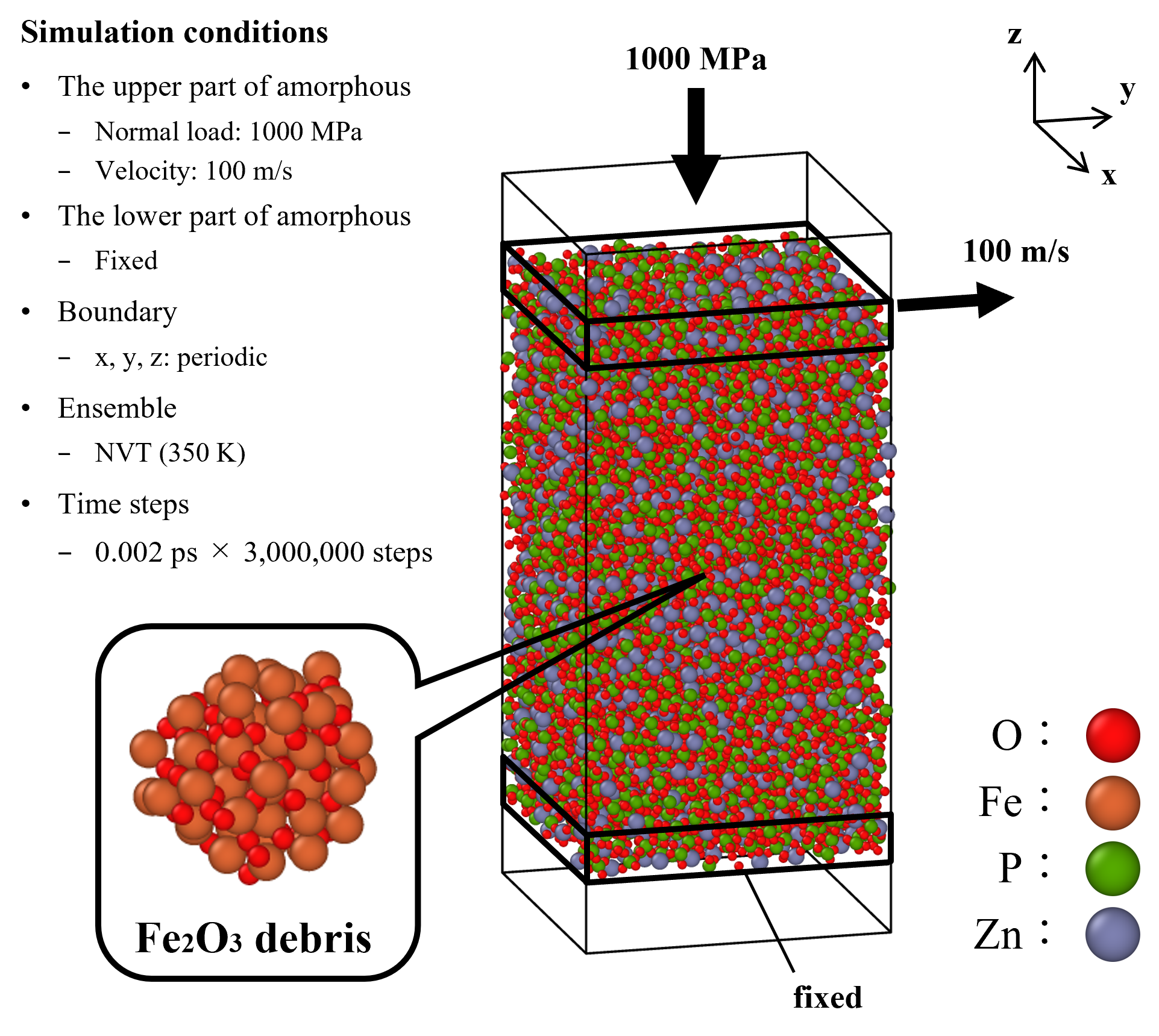
Model for MD simulation of digestion of an iron oxide nanoparticle embedded in ZnDTP tribofilm
Analysis of stenosed arterial flow and contrast agent dynamics using FSI FEM
Transluminal attenuation gradient (TAG) is expected as a noninvasive assessment of the functional significance of a stenosis, and has reported relatively high diagnostic performance. TAG measures the gradient of intraluminal radiological attenuation from the ostium at the first pass of the injected contrast agent; therefore, replacement of fluid by jet flow from a stenosis with gradually increasing contrast agent concentration should be investigated. We performed a phantom experiment and ALE fluid-structure interaction finite element simulation on pulsatile flow through a bifurcated flexible tube system with a stenosis. Experiment and simulation showed good agreement with temporal change of flow rate, pressure, and radius under 1 Hz square pulsatile flow. We varied Young modulus and rate of stenosis with 1 Hz sinusoidal input. Young modulus had little effect on the distribution of total flow, but a changed flow rate waveform and faster maximal velocity in the stenosis was observed with a smaller Young modulus. Then we simulated convection of particle tracers generated at the inlet, imitating a gradual increase in contrast agent with 80% and 95% stenosis. With 80% stenosis, axially symmetric flow resulted in reproductive tracer distributions; however, with 95% stenosis, the direction of jet flow from the stenosis and of subsequent helical flow varied every beat, suggesting this variation might lower sensitivity of TAG.
Reference
- Asuka HATANO, Jun SUMIYOSHITANI, Kazuma SUZUKI, Akihiro GORYU, Akira KANO, Mitsuaki KATO, Kenji HIROHATA, and Satoshi IZUMI. “Phantom experiment and ALE fluid structure interaction analysis of contrast agent dynamics through an elastic stenosis after bifurcation” Transactions of the JSME (in Japanese), Vol. 84, No. 863 (2018)
WEB
SiC oxidation
Silicon carbide (SiC) is an attractive semiconductor material for applications in power electronic devices. However, fabrication of a high-quality SiC/SiO2 interface has been a challenge. It is well-known that there is a great difference in oxidation rate between the Si-face and C-face, and that the quality of oxide on the Si-face is greater than that on thSiCe C-face. However, the atomistic mechanism of the thermal oxidation of SiC remains to be solved. In this paper, a new Si-C-O interatomic potential was developed to reproduce the kinetics of the thermal oxidation of SiC. Using this newly developed potential, large-scale SiC oxidation simulations at various temperature were performed. The results showed that the activation energy of the Si-face is much larger than that of the C-face. In the case of the Si-face, a flat and aligned interface structure including Si1+ was created. Based on the estimated activation energies of the intermediate oxide states, it is proposed that the stability of the flat interface structure is the origin of the high activation energy of the oxidation of the Si-face. In contrast, in the case of the C-face, it is found that the Si atom at the interface are easily pulled up by the O atoms. This process generates the disordered interface and decreases the activation energy of the oxidation. It is also proposed that many excess C atoms are created in the case of the C-face.
Reference
- So Takamoto, Takahiro Yamasaki, Takahisa Ohno, Chioko Kaneta, Asuka Hatano, and Satoshi Izumi, "Elucidation of the atomic-scale mechanism of the anisotropic oxidation rate of 4H-SiC between the (0001) Si-face and (000-1) C-face by using a new Si-O-C interatomic potential", Journal of Applied Physics 123, 185303 (2018).